martedì 7 ottobre 2025

Automation Transforming Heavy Industry Engineering

The integration of automated control systems into mining mechanical engineering has fundamentally altered design verification, performance monitoring, and maintenance strategies. As mining operations demand higher throughput with reduced downtime, automation technologies—from real-time sensor networks to automated inspection protocols—have become critical infrastructure rather than optional enhancements. 

Why Mining Engineers Are Implementing Automated Systems

Mining mechanical systems face unique challenges: high cyclic loads, abrasive material handling, corrosive environments, and remote operational sites. Traditional time-based maintenance schedules often result in either premature component replacement or unexpected failures.

Automated monitoring and inspection systems address these limitations through:

·        Continuous condition assessment without production interruption

·        Objective measurement data eliminating operator variability

·        Early anomaly detection before performance degradation

·        Integration with engineering analysis tools (FEA, fatigue life calculations)

·        Automated documentation for regulatory compliance and failure investigation

The fundamental advantage lies in transitioning from scheduled maintenance to condition-based maintenance grounded in quantitative engineering data (Jardine et al., 2006).

Key Applications of Automation in Mining Mechanical Systems

1. Structural Health Monitoring

Automated strain device networks and accelerometer arrays provide continuous monitoring of critical load-bearing structures:

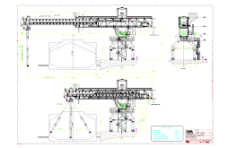
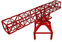
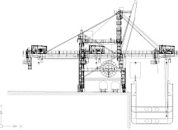
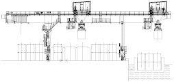
·        Dragline booms and gantries under cyclic loading

·        Haul truck frames experiencing variable payload conditions

·        Conveyor support structures with dynamic loading from material flow

·        Hoisting systems subjected to fatigue-critical duty cycles

Data acquisition systems sampling at 1-10 kHz enable frequency-domain analysis to detect natural frequency shifts indicative of structural degradation or crack propagation (Farrar & Worden, 2007).

2. Rotating Equipment Diagnostics

Automated vibration monitoring systems deployed on crushers, mills, fans, and pumps utilize pattern recognition algorithms to identify:

·        Bearing outer race defects (specific fault frequencies: BPFO = n × RPM × Z/2)

·        Gear mesh anomalies (tooth wear, misalignment, backlash variations)

·        Unbalance conditions from rotor wear or material buildup

·        Resonance conditions approaching critical speeds

Integration with lubrication monitoring systems (oil debris sensors, temperature probes) provides multi-parameter fault detection (Mobley, 2002).

3. Dimensional Verification and Wear Tracking

Automated metrology systems eliminate manual measurement uncertainty:

·        Laser scanning of crusher liners: Quantifying wear rates and predicting replacement intervals based on remaining material thickness

·        Photogrammetry of conveyor idlers: Detecting misalignment and eccentric wear patterns

·        Coordinate measurement of machined components: Statistical process control ensuring dimensional tolerances on critical interfaces (bearing bores, shaft journals, mounting surfaces)

Automated dimensional tracking generates time-series data enabling wear rate modeling and remaining life calculations based on actual degradation rather than assumed service factors.

4. Non-Destructive Testing Integration

Automated NDT systems provide continuous or periodic inspection without disassembly:

·        Ultrasonic thickness monitoring on pressure vessels, hydraulic cylinders, and structural members in corrosive environments

·        Eddy current testing for surface crack detection in high-cycle fatigue areas (hoist ropes, fasteners, shaft keyways)

·        Thermographic inspection identifying thermal anomalies in electrical systems, bearings, and refractory linings

·        Acoustic emission monitoring for real-time crack growth detection in structural welds

Automated data logging creates inspection records for regulatory reporting and failure investigation (Cartz, 1995).

5. Hydraulic System Monitoring

Mining equipment hydraulics operate at 3,000-5,000 psi with contamination from environmental dust and internal wear debris. Automated monitoring systems track:

·        Fluid contamination levels: Particle counters (ISO 4406 classification) detecting abnormal wear rates

·        Pressure transients: High-speed data acquisition identifying cavitation, valve surge, or actuator loading

·        Temperature profiling: RTD networks detecting inefficient heat rejection or flow restrictions

·        Flow measurement: Identifying internal leakage or pump degradation

Automated alert systems trigger maintenance interventions based on predefined thresholds before catastrophic failure.

Real-World Implementation: Automated Fatigue Life Assessment

Consider a mine site operating ten haul trucks with instrumented suspension systems. Each truck generates continuous strain data from multiple load cells and accelerometers during operation.

Manual approach limitations:

·        Engineers periodically download data and process in spreadsheet software

·        Fatigue damage calculations performed on sample datasets

·        Analysis delayed by weeks, missing early failure indicators

Automated system capabilities:

·        Real-time rainflow counting algorithms calculate fatigue damage accumulation

·        Cloud-based processing compares actual load spectra against design assumptions

·        Automated alerts when cumulative damage exceeds threshold percentages

·        Predictive algorithms forecast remaining component life based on current usage patterns

A Python-based automated analysis pipeline processes strain data using rainflow counting algorithms and applies Miner's rule for damage summation (Dowling, 2013). Results populate dashboards accessible to maintenance planners, enabling proactive component replacement scheduling.

Data Integration and Decision Support

Automated systems generate substantial data volumes requiring structured management:

·        Historian databases: Time-series data storage (OSIsoft PI, InfluxDB) with compression algorithms

·        Edge processing: Local computation reducing network bandwidth requirements

·        Cloud analytics: Centralized processing for multi-site equipment fleets

·        API integration: Connection to ERP systems (SAP, Oracle) for automated work order generation

Engineering teams utilize this infrastructure to:

·        Compare equipment performance across multiple sites

·        Identify design weaknesses appearing in fleet-wide datasets

·        Validate design modifications through before/after analysis

·        Generate technical reports for regulatory submissions

Predictive Maintenance and Machine Learning

Advanced implementations incorporate machine learning algorithms to improve failure prediction accuracy. Supervised learning models trained on historical failure data can identify subtle patterns in sensor data that precede component failures (Susto et al., 2015). Common approaches include:

·        Random forests for classification of equipment health states

·        Support vector machines for anomaly detection in vibration signatures

·        Neural networks for remaining useful life prediction

·        Time-series analysis (ARIMA, LSTM) for trending and forecasting

Model validation requires careful consideration of training data quality, feature selection, and cross-validation to prevent overfitting. Engineering judgment remains essential in interpreting model outputs and establishing appropriate alert thresholds.

Conclusion: Engineering Discipline in Automation Implementation

Automation systems provide mining mechanical engineers with quantitative, time-stamped data enabling evidence-based maintenance decisions. Successful implementation requires careful consideration of sensor selection, data acquisition architecture, signal processing methods, and integration with existing engineering workflows.

The transition from reactive to predictive maintenance depends on disciplined data collection, appropriate statistical analysis, and engineering judgment in interpreting automated system outputs. When properly implemented, these systems reduce unplanned downtime, extend component life, and provide objective documentation for continuous improvement initiatives (Mobley, 2002).

For mechanical engineers in the mining sector, automation represents not a replacement for engineering analysis, but rather an enhancement—providing the measurement infrastructure necessary to validate design assumptions, quantify actual operating conditions, and optimize maintenance strategies based on equipment-specific performance data rather than generic industry guidelines.

Explore our solutions and see how IDECO supports heavy industry engineering with cutting-edge control and verification tools.

ideco@ideco.group

www.ideco.group


References

Cartz, L. (1995). Nondestructive testing: Radiography, ultrasonics, liquid penetrant, magnetic particle, eddy current. ASM International.

Dowling, N. E. (2013). Mechanical behavior of materials: Engineering methods for deformation, fracture, and fatigue (4th ed.). Pearson.

Farrar, C. R., & Worden, K. (2007). An introduction to structural health monitoring. Philosophical Transactions of the Royal Society A: Mathematical, Physical and Engineering Sciences, 365(1851), 303-315. https://doi.org/10.1098/rsta.2006.1928

Jardine, A. K. S., Lin, D., & Banjevic, D. (2006). A review on machinery diagnostics and prognostics implementing condition-based maintenance. Mechanical Systems and Signal Processing, 20(7), 1483-1510. https://doi.org/10.1016/j.ymssp.2005.09.012

Mobley, R. K. (2002). An introduction to predictive maintenance (2nd ed.). Butterworth-Heinemann.

Susto, G. A., Schirru, A., Pampuri, S., McLoone, S., & Beghi, A. (2015). Machine learning for predictive maintenance: A multiple classifier approach. IEEE Transactions on Industrial Informatics, 11(3), 812-820. https://doi.org/10.1109/TII.2014.2349359


giovedì 14 agosto 2025

Structural Failure Analysis and Material Flow Optimization: Two Critical Case Studies in Bulk Material Handling

Engineering Case Studies: Bulk Material Handling

As mechanical engineers working in bulk material handling, we frequently encounter complex challenges that require both analytical rigor and innovative problem-solving approaches. Today, we'll examine two real-world case studies that demonstrate how systematic engineering analysis can transform operational failures into reliable, optimized systems.

Case Study 1: Bucket Wheel Stacker/Reclaimer Structural Failure

The Problem

A bucket wheel stacker/reclaimer experienced a critical structural failure at the connection between the gantry and traveling system. This type of failure poses significant safety risks and can result in extended downtime, making it a priority for immediate analysis and remediation.

Bucket wheel stacker structural failure

Root Cause Analysis

Using Finite Element Method (FEM) analysis, the investigation revealed that the failure occurred due to the absence of an internal diaphragm at the section reduction point. This missing structural element created a stress concentration that exceeded the material's capacity under operational loads.

The FEM analysis clearly highlighted how the section transition without proper internal reinforcement led to inadequate load distribution and subsequent structural compromise. This finding underscores the critical importance of proper structural continuity in heavy machinery design.

FEM analysis drawing Analysis diagram Technical drawing

Engineering Solution

Given the operational constraints of the existing equipment, installing a traditional internal diaphragm was not feasible. The engineering team developed an innovative approach: implementing external reinforcement that provides equivalent structural resistance to the missing internal diaphragm.

This solution demonstrates the flexibility required in retrofit engineering projects, where ideal theoretical solutions must be adapted to real-world constraints while maintaining structural integrity.

Implementation

The final phase involved producing detailed workshop drawings for the external reinforcement system. This documentation ensured that the fabrication and installation would meet the calculated structural requirements while being practical for field implementation.

Workshop drawing

Case Study 2: Coal Hopper Flow Optimization

The Challenge

A coal handling facility was experiencing recurring operational shutdowns due to material clogging in the hopper system. The material would overflow, requiring manual intervention and plant shutdowns – a costly and inefficient operational scenario.

Coal hopper clogging issue Hopper system

Technical Analysis

The investigation revealed multiple contributing factors:

  1. Material adhesion: Coal was gradually sticking to the hopper walls, progressively reducing the effective flow area
  2. Incorrect wall angles: The chute walls were designed without proper consideration of the material's angle of repose and complementary angles
  3. Undersized sections: The chute geometry was inadequate for the material flow requirements

Advanced Simulation Approach

The engineering team employed Discrete Element Method (DEM) simulation to model the material properties and analyze flow behavior. This computational approach allowed for:

  • Accurate prediction of particle behavior under various geometric configurations
  • Optimization of wall angles based on actual material properties
  • Validation of proposed solutions before physical implementation
DEM simulation

Validation and Standards Compliance

Critical to the project's success was the validation of DEM calculations against established engineering standards. This step ensures that simulation results translate reliably to real-world performance and meet industry requirements.

Optimized Design Solution

Based on the simulation results, a new discharge system was developed that addressed all identified issues:

  • Proper wall angles accounting for material characteristics
  • Optimized section sizing for adequate flow capacity
  • Surface treatments to minimize material adhesion

Key Engineering Takeaways

1. Systematic Analysis is Essential

Both cases demonstrate the importance of thorough root cause analysis. Rather than implementing quick fixes, systematic investigation using appropriate analytical tools (FEM for structural issues, DEM for material flow) leads to more effective and lasting solutions.

2. Simulation Tools Enable Better Design

Modern computational tools like FEM and DEM simulation allow engineers to understand complex behaviors that would be difficult or impossible to analyze using traditional methods. These tools enable optimization before physical implementation, reducing risk and cost.

3. Practical Constraints Shape Engineering Solutions

The bucket wheel case illustrates how engineering solutions must balance theoretical ideals with practical constraints. Sometimes the best engineering solution isn't the most obvious one, but rather the one that can be effectively implemented within existing limitations.

4. Material Properties Drive Design

The hopper case emphasizes how critical it is to understand and incorporate actual material properties into design decisions. Generic approaches often fail when material-specific characteristics like angle of repose, particle size distribution, and adhesive properties aren't properly considered.

5. Validation Ensures Reliability

Both projects included validation steps – whether through standards compliance or field verification. This validation phase is crucial for ensuring that analytical results translate to reliable operational performance.

Optimized design results

Conclusion

These case studies illustrate the multidisciplinary nature of modern mechanical engineering in bulk material handling. Success requires not only strong analytical capabilities but also practical problem-solving skills, advanced simulation tools, and a thorough understanding of material behaviors.

For mechanical engineers working in similar applications, these examples highlight the value of:

  • Comprehensive failure analysis using appropriate computational tools
  • Creative problem-solving when standard solutions aren't feasible
  • Material-specific design approaches rather than generic solutions
  • Rigorous validation against established standards

The integration of advanced analysis tools with practical engineering judgment continues to be the foundation of successful bulk material handling system design and optimization.

The case studies presented here demonstrate real-world applications of engineering analysis in bulk material handling systems. For complex projects requiring similar expertise, consulting with specialized engineering firms can provide the analytical depth and practical experience necessary for successful outcomes.

martedì 20 maggio 2025

Beyond the Blueprint: Ensuring Design Integrity from Conception to Decommissioning


For mechanical engineers, the journey of a machine or component extends far beyond the initial design phase. While sophisticated 3D modeling and Finite Element/Discrete Element Method (FEM/DEM) software empower us to create intricate and highly specific designs, these very complexities can introduce challenges during manufacturing. Discrepancies between the digital twin and the physical reality can lead to costly errors, production delays, and ultimately, compromised performance.

At IDECO Heavy Equipment, we understand this critical juncture. Our mechanical engineering philosophy is rooted in a comprehensive approach that spans the entire lifecycle of your project, ensuring that the initial design intent is flawlessly translated into a functional and reliable final product. Our commitment doesn't end when the drawings leave our office; it continues until the very decommissioning of the equipment.


Bridging the Gap: From Virtual Precision to Physical Accuracy

The potential for divergence between design and manufacturing is a significant concern. The intricate geometries and tight tolerances achievable with advanced software can present hurdles for fabrication. This is where IDECO's unique three-phase engineering process truly shines:

1. OFFICE PHASE: The Foundation of Success

This initial stage culminates in the comprehensive documentation required for manufacturing. We leverage cutting-edge design tools to create detailed blueprints and specifications. Crucially, we go a step further by producing scaled physical models using professional 3D printers. This tangible verification allows us to identify potential manufacturing challenges early, mitigating risks and ensuring the design is practically realizable.

2. WORKSHOP PHASE: Ensuring Design Fidelity in Reality

This is where IDECO distinguishes itself. While many engineering firms conclude their involvement after delivering the manufacturing documents, for us, this is where a critical second phase begins. We employ state-of-the-art metrology tools and software to meticulously verify that the manufactured component precisely matches the intended design.

Our scope includes:

  • Certified 3D Scanners: To create accurate digital replicas of the manufactured parts.

  • UT Thickness Meters: For non-destructive measurement of material thickness.

  • Advanced Metrology Software: Enabling direct comparison between the original 3D model and the scanned manufactured component, ensuring dimensional and geometrical tolerances are met.

  • Non-destructive RX Metal Analyzer: To confirm the chemical composition of the materials used aligns with the specifications in the calculation report.

  • Digital Hardness Meter: To verify the mechanical characteristics of the materials.

  • Ultrasound Flaw Detector: For inspecting welds and materials, guaranteeing structural integrity and adherence to quality standards.

  • Surface Roughness and Hardness Testers: To confirm the final surface properties meet design requirements.

3. PLANT PHASE: Optimizing Performance Throughout the Lifespan

Our commitment extends beyond initial manufacturing. We conduct thorough checks on the assembled machine, utilizing advanced tools such as:

  • Noise and Vibration Analysis Equipment: To ensure operational parameters align with design specifications.

  • Thermal Imaging Cameras: To identify potential overheating issues stemming from mechanical friction, fluid dynamics, or electrical faults (Joule effect).

The data gathered during this phase is integrated into the project calculation report, providing the customer with a comprehensive understanding of the machine's performance characteristics. Furthermore, we offer ongoing design reviews to adapt the machine to evolving production needs throughout its operational life. Our involvement only concludes when the machine is finally decommissioned.

The IDECO Advantage: Mitigating Manufacturing Risks and Ensuring Long-Term Reliability

Our commitment delivers tangible benefits:

·        Fewer Errors & Reworks: Early validation minimizes surprises during manufacturing

·        Higher Reliability: Stringent checks maintain design and safety standards

·        Lower Downtime: Predictive assessments reduce unexpected failures

·        End-to-End Support: We’re there from the first sketch to decommissioning

Is Your Internal Engineering Team Facing Capacity Challenges?

In today's demanding industrial environment, even the most capable internal engineering teams can face limitations due to workload, specialized expertise requirements, or the need for unbiased third-party verification. Recognizing these limitations is not a sign of weakness but a strategic opportunity to enhance your operations.

Three Signs Your Internal Engineering Team Could Benefit from Reinforcement:

  1. Capacity Overload: Are your engineers constantly juggling priorities, leading to delayed response times and project slippage?

  2. Increased Error Rates: Are you noticing more mistakes, rework, or quality issues that might be a symptom of an overstretched team?

  3. Missed Deadlines: Are critical project milestones consistently being pushed back, impacting timelines and budgets?

It's Not a Replacement, It's Reinforcement.

Partnering with IDECO is not about replacing your internal engineering capabilities; it's about augmenting them. We act as an extension of your team, providing specialized expertise and additional bandwidth to ensure your projects are executed flawlessly from design to decommissioning.

Ready to elevate your mechanical engineering projects and ensure seamless translation from design to reality?

Contact IDECO Heavy Equipment today to discuss how our comprehensive three-phase engineering process and experienced team can provide the reinforcement your internal team needs to thrive.

ideco@ideco.group